Part II: Basic 2D Views and Protocols
The widespread clinical acceptance of 2D imaging has tremendously aided the diagnostic results of a typical echocardiographic examination. Improved transducer design, resolution capabilities, focus parameters, gray-scale differentiation, gain control factors, cine loop functions, and other software capabilities have aided the cardiac sonographer in the attempt to record consistent, high-quality images from the multiple scan planes necessary to obtain a dynamic composite image of the cardiac structures. Color flow and spectral Doppler allows the practitioner to obtain additional velocity information to detect intracardiac shunt flow, “map” regurgitant jet flow, and determine obstructive flow pathways.
The evaluation of cardiac structures by echocardiography is regarded as an essential diagnostic tool in clinical cardiology. The reason for its widespread use in the evaluation of cardiac disease is its noninvasive, reproducible, and accurate assessment of cardiac structures. Echocardiography exploded when two-dimensional (2D) echocardiography was developed, which allowed the cardiac structures to be dynamically visualized in real-time. Thus, the echocardiographer can assess the four chambers of the heart, the cardiac valves, the intracardiac anatomy, and the intracardiac lesions; observe contractility; determine valvular function; and assess hemodynamics. The combination of 2D, Doppler, tissue Doppler imaging, strain, and color flow mapping provides an extremely accurate means to evaluate wall or valve thickness, valvular orifice and chamber size, and contractility of the cardiac structures. The introduction of transesophageal echocardiography (TEE) and three-dimensional (3D) echocardiography has enabled exquisite visualization of the heart while the transducer is guided through the mouth and into the esophagus to image detailed cardiac anatomy.
Contrast injected through an intravenous line into the bloodstream has provided an additional pathway to enhance cardiac endocardial borders and demonstrate cardiac thrombus and mass lesions; whereas saline bubble injections have been a clinical aid to determine the presence and direction of interatrial septal shunt flow.
This discussion introduces the reader to the basic technical components of two-dimensional (2D)echocardiography. Following this you can take the course on Spectral and Color Flow Doppler (CFD) imaging.
Examination Techniques
To begin the echocardiographic procedure, the patient is examined in the left lateral decubitus position. (Figure 1)

This position allows the heart to move away from the sternum and closer to the chest wall, thus allowing a better “cardiac window”. The cardiac window may be considered that area on the anterior chest where the heart is just beneath the skin surface, free of lung interference and is usually found between the third and fifth intercostal spaces, slightly to the left of the sternal border.
The cardiac sonographer must keep in mind that different body shapes require variations in transducer position. An obese patient may have a horizontal transverse heart, and thus a slight lateral movement from the sternal border may be needed to record cardiac structures. A thin patient may have a long and slender heart, requiring a lower, more medial transducer position. Barrel-chested patients may have echocardiographic difficulties because of the lung absorption interference and it may be necessary to turn these patients completely on their left side. Sometimes the upright or slightly forward-bent position is useful in forcing the heart closer to the anterior chest wall.
The following techniques are guidelines for the average patient. In the initial echocardiographic study, slowly move the transducer freely along the mid-left sternal border until all the cardiac structures are easily identified is generally a better practice than restricting the transducer to one intercostal space. This procedure saves time and gives the examiner a better understanding of cardiac relationships. If the heart is actually medial, the best study is performed with the patient completely on his or her left side. Observing the patient’s respiratory pattern may help the sonographer identify if the lungs overshadow the cardiac structures. Controlled breathing will help to obtain good quality images. If the lung interference clouds the cardiac structures, the patient should breathe in and then exhale for as long as possible to move the lungs away from the field of view. This usually gives the examiner adequate time to record valid information.
Transducers. Several types of transducers are available for echocardiographic techniques. Most adult cardiac sonographers use a small diameter sector multifocal transducer that ranges from 1.5- to 4.5-MHz transducer for the echocardiography procedure.
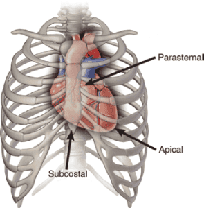
Transducer Location and Imaging Planes. The Committee on Nomenclature and Standards in Two-Dimensional Echocardiography of the American Society of Echocardiography recommends the following nomenclature and image orientation standards for transducer locations, (Figure 2).

● Suprasternal. Patient is supine with head tilted back. Transducer placed in the suprasternal notch.
● Subcostal. Patient is supine. Transducer located near the body midline and beneath the costal margin. As the patient takes in a breath, the transducer is tilted cephalad to image the four chambers of the heart.
● Apical. Patient in left lateral decubitus position. Transducer is placed over the cardiac apex (at the point of maximal impulse).
● Parasternal. Patient in left lateral decubitus position. Transducer placed along the left sternual border, usually in the 3rd, 4th, or 5th intercostal space.
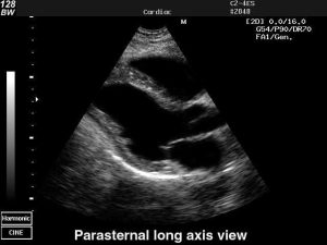
The imaging planes are described by the manner in which the two-dimensional transducer transects the heart, (Figure 3).
● Parasternal Long Axis (PLA). Transects the heart perpendicular to the dorsal and ventral surfaces of the body and parallel with the long axis of the heart.
● Parasternal Short Axis (PSA). Transects the heart perpendicular to the dorsal and ventral surfaces of the body and perpendicular to the long axis of the heart.
● Apical Four chamber view (4CV). Transects the heart approximately parallel with the dorsal and ventral surfaces of the body.
| Transducer Position and Cardiac Protocol | |
|---|---|
| Parasternal | Long axis view Short axis view |
| Apical | Four chamber view Five chamber view (incl. aorta) Three-chamber view (incl. aorta) Two-chamber view |
| Subcostal Window | Inferior vena cava, hepatic veins RV and LV inflow LV, aorta RV outflow |
| Suprasternal Notch Window | Ascending aorta Descending aorta Right pulmonary artery Left atrium |
| Right Parasternal Window | Ascending aorta |
The examination
It is the responsibility of the cardiac sonographer to acquire the patient’s blood pressure and height/weight (to calibrate the body surface area) of each patient. Ideally, the sonographer should digitally acquire the cine loop of one or more cardiac cycles as needed for quantification and analysis. If an irregular rhythm is present (i.e., atrial fibrillation, flutter, or frequent ectopy), the sonographer should acquire 3 to 5 consecutive cardiac cycles for 2D; Doppler will need 4 to 10 consecutive beats averaged. If two or more myocardial segments of the left ventricle are not well visualized, the use of an approved injectable contrast agent, such as Definity, should be considered if no contraindications are present. The sonographer should always compare the echocardiographic images to the previous study when preparing the preliminary report.
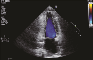
The protocol for the evaluation cardiac structures begins with the parasternal long- and short-axis views, followed by the apical four-chamber, long-axis, and two-chamber views, (Figure 4).

The subcostal and suprasternal views complete the study. The sonographer should acquire the respective cine loop(s) for 2D and color flow Doppler and acquire the representative still frames for M-modes and PW/CW Doppler.
The following protocol is a minimum standard to be performed for all adult complete 2D/M-mode, color flow Doppler (CFD), and spectral Doppler exams. Additional views are often required and are based on presence of disease and clinical indications. The order of acquisition is important and should always follow this sequence: (1) 2D image, then (2) full screen color flow Doppler of same image, followed by (3) spectral Doppler of the same view. The intent is to show anatomy first (zoom as needed), then color flow of that anatomy (zoom as needed), then spectral. Labeling views or structures is strongly recommended whenever there is an interruption in the 2D/CFD/Spectral format or if nonstandard images are used. Either mode may not increase frame rate depending on harmonic frequency selection. The sonographer should digitally acquire the following views in the order listed below.
Parasternal Views
Parasternal Long-Axis View of the Left Ventricle
The parasternal long-axis view (PLA) is the initial image in the complete echographic examination. An attempt should be made to record as many of the cardiac structures as possible, from the base of the heart to the apex. The transducer “notch” or groove should be facing toward the patient’s right shoulder. Generally, this is accomplished by placing the long axis of the transducer slightly to the left of the sternum in the third or fourth intercostal space. Thus the transducer beam should be directed from the right shoulder to the left hip to observe the long axis view of the heart. The image should display the aorta to the right, the cardiac apex to the left, and the chest wall and right ventricle should be seen anteriorly. When the bright echo reflection of the pericardium is noted, the transducer is gradually rotated until a clear long-axis view of the heart is obtained. This view will demonstrate the right ventricle, aorta/ascending aorta, left atrium, mitral leaflets, interventricular septum, and left ventricle, see Figure 5.

The parasternal long axis view of the left ventricle also shows the aortic root and ascending aorta. With the onset of systole, the aortic leaflets open fully to parallel the aortic walls. The left atrial cavity is seen posterior to the aorta. The left inferior pulmonary vein may be seen to enter the posterior aspect of the atrial cavity. The circular descending aorta is seen posterior to the left atrial cavity. The anterior and posterior mitral leaflets, chordal and papillary muscle attachments may also be seen. The anterior leaflet of the mitral valve should be contiguous with the posterior wall of the aorta (Figure 6).

The coronary sinus appears as a small circular sonolucent structure in the area of the posterior atrioventricular groove. If the coronary sinus is enlarged, a persistent left-sided superior vena cava or increased right atrial pressure should be suspected. A left-sided superior vena cava can be confirmed by opacification of the coronary sinus with the injection of agitated saline in the left arm. The left ventricular outflow tract is bordered by the interventricular septum anteriorly and the anterior leaflet of the mitral valve posteriorly. If it is not possible to record the entire long axis on a single scan, the transducer should be gently rocked cephalad to caudad in an “ice pick” fashion to record all the information from the base to the apex of the heart.
Parasternal long axis view of the Right Ventricular Inflow.
With the transducer in the same intercostal space, a long axis view of the right ventricle and right atrium is obtained by tilting the transducer inferomedially and rotating it slightly clockwise. This medial angulation of the probe in the PLA will demonstrate the tricuspid valve, right ventricle, and right atrium (Figure 7).


closed.
The patient position may need to be adjusted in order to see the anterior wall of the right ventricle clearly. In this view, the image is oriented with the chest wall anterior, the right atrium is on the right, separated by the tricuspid leaflets, and the right ventricle is on the left. The entry of the coronary sinus (CS) may also be seen. This view of the RV inflow is good to record the velocity of tricuspid regurgitation.
The cardiac sonographer should observe the following structures and functions in the parasternal long-axis view:
• Composite size of the cardiac chambers
• Contractility of the right and left ventricles
• Thickness of the right ventricular wall
• Continuity of the interventricular septum with the anterior wall of the aorta
• Pliability of the atrioventricular and semilunar valves
• Coaptation of the atrioventricular valves
• Presence of increased echoes on the atrioventricular and semilunar valves (increased echoes may represent calcification, fibroelastoma, vegetations, or other abnormality)
• Systolic clearance of the aortic cusps (aortic leaflets should open fully in systole)
• Presence of abnormal echo collections in the chambers or attached to the valve orifice (thrombus may occur if there are wall motion abnormalities)
• Presence and movement of chordal-papillary muscle structure
• Thickness of the septum and posterior wall of the left ventricle
• Uniform texture of the endocardium and myocardium
• Size of the aortic root and left atrium
• M-mode of the aortic root/left atrium; mitral leaflets, and left ventricle (Figure 8)
• Evaluation of the aortic root, aortic sinus, and ascending aorta (Figure 9)


ventricle C.

Parasternal Short-Axis Views
The transducer should be rotated 90 degrees clockwise from the parasternal long-axis view to obtain multiple transverse short-axis views of the heart, particularly at the following four levels described below. The notch or groove on the transducer is pointed superiorly to face the right supraclavicular fossa. With the beam perpendicular to the chest, the landmark should be the mitral valve leaflets clearly seen within the left ventricular cavity. The crescent shaped right ventricle should be anterior and to the left.
1. With the probe angled slightly inferior, the low parasternal short-axis view, (Figure 10) should demonstrate the right ventricle, interventricular septum, left ventricle, and papillary muscles (chordal echoes may also be seen):


The cardiac sonographer should observe the following structures and functions in the inferior parasternal short-axis view:
a. Contractility of the septum and posterior wall of the left ventricle
b. Thickness of the septum and posterior wall
c. Size of the left ventricle
d. Presence or absence of mural thrombus or other mass
e. Presence or absence of pericardial fluid, constriction, or restriction
f. Presence of increased echo density in posterior wall
g. Number of papillary muscles and their location within the left ventricular cavity
2. With the transducer perpendicular to the chest wall, the mid-parasternal short-axis view, (Figure 11) should demonstrate the right ventricle, left ventricular outflow tract, and anterior and posterior leaflets of the mitral valve

mitral valve; LVOT, left ventricular outflow tract

The anterior and posterior mitral valve leaflets are further assigned arbitrary identification labels for accurate description of the leaflet, see (Figure 12). The lateral aspect of the anterior and posterior leaflets are A1 and P1 respectively. The medial aspect of the leaflets are A3 and P3. The mid-leaflets are A2 and P2. You will note that the specific part of the leaflet will vary with the different transducer positions. This nomenclature is especially helpful in describing the exact area of abnormality.

The cardiac sonographer should observe the following structures and functions in the mid-parasternal short-axis view:
a. Size of the left ventricular outflow tract
b. Size of the septum and posterior wall
c. Presence of mass lesions in left or right ventricle
d. Mobility and thickness of the mitral valve
e. Presence of a flutter on the septum or anterior leaflet of the mitral valve or both
f. Systolic apposition of mitral valve leaflets
g. Contractility of septum and posterior wall
3. The probe should be angled slightly towards the right shoulder for the moderate to high parasternal short-axis view, (Figure 13), should demonstrate the right ventricle, tricuspid valve, aortic cusps, coronary arteries, right and left atria:


The cardiac sonographer should observe the following structures and functions in the high-parasternal short-axis view:
a. Size of right ventricle and left atrium
b. Presence of mass lesions in right or left atrium
c. Mobility and thickness of tricuspid and aortic valves
d. Continuity of interatrial septum
e. Right ventricular wall thickness
f. Presence of trileaflet aortic valve
4. Slight angulation toward the right shoulder in the high parasternal short-axis view, (Figure 14), should demonstrate the pulmonary valve, right ventricular outflow tract, and aorta. It may help to move the probe up an interspace to see the pulmonary leaflets clearly.


The cardiac sonographer should observe the following structures and functions in the high-parasternal short-axis view directed to image the pulmonary artery:
a. Typical sausage-shaped right ventricular outflow tract and pulmonary artery draped anterior to circular aorta
b. Semilunar cusp thickness and mobility
c. Presence of calcification, extraneous echoes, or both in right ventricle or valve areas
d. Pulmonary valve mobility and thickness
5. The high parasternal short-axis view, (Figure 15), is also useful to demonstrate the right ventricular outflow tract, tricuspid leaflets, and right atrium. The transducer should be angled medial from the pulmonary artery to image the tricuspid leaflets.

Apical Views
Apical 2D Views
Three apical views are very useful: the four-chamber view, the two-chamber view, and the apical long-axis view. The cardiac sonographer should palpate the patient’s chest to detect the point of maximal impulse (PMI). The transducer should then be directed in a transverse plane at the PMI and angled sharply cephalad to record the four chambers of the heart. The notch of the transducer should be directed toward the right shoulder. If there is too much lung interference, then the proper cardiac window has not been found and care should be taken to adjust the patient’s position or the transducer position to adequately see all four chambers of the heart. Many laboratories have found it useful to use the special echocardiographic bed in which a dropout section of the bed beneath the chest enables the sonographer to readily access the cardiac apex. This allows the sonographer to maintain more flexibility with the transducer to image the apical views.
The apical views are excellent to assess cardiac contractility, size of cardiac chambers, presence of mass lesions, alignment of atrioventricular valves, coaptation of atrioventricular valves, analyze septal or posterior wall hypertrophy, assess chordal attachments, and evaluate the presence of pericardial effusion. It may be more difficult to obtain an adequate image from the apical view than from the parasternal views, thus patience and perseverance is required to master this skill. This is because the ribs may interfere with the probe access to image the cardiac structures without artifacts or lungs interfering with the sound beam transmission. Once the perfect cardiac window has been located, the sonographer should carefully sweep the probe slightly anterior to posterior to be sure the ventricles are not foreshortened. The effort is made to elongate the ventricular cavity to show the thin apical segment, (Figure 16).

If the ventricle appears “roundish”, the probe should be directed more posterior to “open up” the ventricular cavity. Another method is to move the probe inferior to the next intercostal space to obtain the true apex of the heart. Breathing, the patient really helps with these views in the apex. The goal is to watch what happens to the lungs when the patient takes in a breath and lets their breath out. Practice with breathing techniques on every patient will help your images become stellar.
Apical Four Chamber view
The four chamber view does not provide a good window to evaluate the presence of an atrial septal defect because the beam is parallel to the thin foramen ovale and the septum commonly appears as an “artifactual defect” in this view. The subcostal four-chamber view is much better for evaluating the presence of such a defect.
The cardiac sonographer should observe the following structures in the apical view:
• Size of the cardiac chambers
• Contractility of right and left ventricles
• Septal and posterior wall thickness, contractility, and continuity
• Coaptation of atrioventricular valves
• Alignment of atrioventricular valves
• Presence of increased echoes on valve apparatus
• Presence of mass or thrombus in cardiac chambers
• Entrance of pulmonary veins into left atrial cavity
• Size of left ventricular outflow tract, signs of obstruction, mobility of aortic cusps, absence of subaortic membrane
• Entrance of inferior and superior vena cava into the right atrium
The apical four chamber allows good visualization of the left atrial cavity and pulmonary venous inflow. It also provides excellent visualization of the mitral valve inflow patterns at rest and with Valsalva to assess diastology. Doppler Tissue Imaging (DTI) is useful to quantify diastolic parameters. Pulmonary venous inflow is also recorded from this view. Analysis of the right heart and tricuspid valve is made in the apical four chamber view,
Apical Five Chamber view
From the four chamber view, the probe is slightly angled anterior to obtain the “five chamber view, (Figure 17).


This view outlines the left ventricular outflow tract, aortic root and leaflets, and the ascending aorta.
Apical Two Chamber view
To obtain the apical two chamber view, (Figure 18), the transducer is rotated 90 degrees from the apical four chamber view to visualize the left ventricle, left atrium, and mitral valve. The anterior and posterior walls of the left ventricle are well seen.


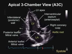
Apical Three Chamber or Apical Long Axis view
The apical long-axis view is very useful for evaluation of the left ventricular cavity and aortic outflow tract (Figure 19).
From the two chamber view, the transducer is angled slightly anterior and medial to see the left ventricular outflow tract and ascending aorta. This view permits the cardiac sonographer to evaluate the wall motion of the posterior basal segment of the left ventricle, the septal wall, and the apex of the left ventricle. It also permits another view of the left ventricular outflow tract, which may be useful in determining aortic cusp motion or the presence of a subvalvular membrane.

Subcostal Views
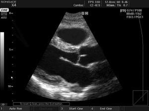
Subcostal Two-Dimensional View
The subcostal view also has multiple windows in the four-chamber and short-axis planes. Many of the views are only available in the pediatric patient (because of the flexible abdominal muscles). The subcostal four-chamber view is generally useful in many adults and may serve as an alternative view if the apical four-chamber view is unobtainable. The transducer should be placed in the subcostal space and, with moderate pressure applied, angled steeply toward the patient’s left shoulder. The plane of the transducer is transverse for visualization of the four chambers of the heart.
It is usually easy to follow the inferior vena cava into the right atrium of the heart. With careful angulation, the interatrial septum may be visualized between the anterior right atrial chamber and the posterior left atrial chamber (Figure 20).


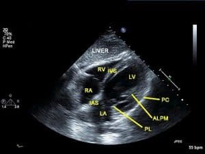
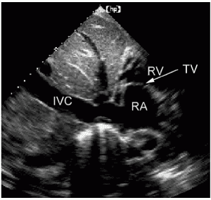
vena cava is made with the transducer midline or slightly angled to the right.

It is usually more difficult to open the right ventricular cavity in this view; therefore, no size assessment should be made. This view is usually very good for assessing the presence of pericardial effusion, especially because it surrounds the anterior segment of the right side of the heart.
Suprasternal Views
Suprasternal Two-Dimensional View
In the suprasternal view, the transducer is directed transversely in the patient’s suprasternal notch and angled steeply toward the arch of the aorta (Figure 21).

The notch of the transducer should be directed toward the right supraclavicular region.
This view is only useful if the transducer is small enough to fit well into the suprasternal notch. The patient is best prepared if several towels or a pillow are placed under the shoulders. In this position the patient’s neck should flex, avoiding interference with the neck of the transducer and cable. The patient’s head should be turned to the right, again to avoid interference with the cable. With careful angulation, the cardiac structures visualized are the ascending aorta, aortic arch, descending aorta, brachiocephalic vessels, right pulmonary artery, left atrium, and left main bronchus (Figure 22A-B). This view is especially useful in determining supravalvular enlargement of the aorta, coarctation of the aorta, or dissection of the aorta. The right pulmonary artery is visualized as a circle posterior to the ascending aorta and under the arch of the aorta. The left atrium is seen posterior to the right pulmonary artery.
The short axis view of the aortic arch is obtained by rotating the transducer clockwise with the groove facing posterior towards the patient’s trachea. This view will demonstrate the ascending aorta superior and the long axis of the right pulmonary artery inferior. As the transducer is rotated slightly clockwise with a slight cephalic tilt, the distal main pulmonary artery is seen (Figure 22C-D). The left atrial cavity is posterior to the pulmonary artery. The superior vena cava may be seen to the left alongside the aorta.
 |
 |
| Figure 22A. | Figure 22B. |
 |
 |
| Figure 22C. | Figure 22D. |
| Figure 22 A. Transducer position for the suprasternal notch view. B. Transverse suprasternal notch view of the superior vena cava (SVC) as it lies to the right of the arch of the aorta. The right pulmonary artery (RPA) is posterior to the arch of the aorta. LPA, Left pulmonary artery. C. Short axis suprasternal notch view of the ascending aorta, SVC, RPA, and main pulmonary artery. D. Suprasternal long view of the ascending, arch, and descending aorta. The right pulmonary artery is posterior to the arch. | |
References
- ASE GUIDELINES; Recommendations for Cardiac Chamber Quantification by Echocardiography in Adults: An Update from the American Society of Echocardiography and the European Association of Cardiovascular Imaging, JASE, January 2015
- ASE GUIDELINES: Guidelines for the Echocardiographic Assessment of the Right Heart in Adults, JASE, July 2010
- ASE GUIDELINES: Current and Evolving Echocardiographic Techniques for the Quantitative Evaluation of Cardiac Mechanics: ASE/EAE Consensus Statement on Methodology and Indications, JASE, March 2011
- Garner CJ, Brown S, Hagen-Ansert S: Guidelines for cardiac sonographer education, J Am Soc Echocardiogr 5:635, 1992.
- Hagen-Ansert, SL. Textbook of Diagnostic Sonography 8th E., Elsevier, St. Louis, 2017.
- Oh, JK, Seward JB, Tajik, AJ. The Echo Manual, Wolters Kluwer, Lippincott Williams & Wilkins, 2006.
- Otto C: Textbook of clinical echocardiography, ed 4, Philadelphia, 2009, Saunders.
- Otto C: Valvular heart disease: a companion to Braunwald’s heart disease, ed 3, Philadelphia, 2010, Saunders.